Author: GRID Skola

  • SVC or STATCOM? How Engineers Actually Choose a Reactive Power Compensator at the PCC.

    SVC or STATCOM? How Engineers Actually Choose a Reactive Power Compensator at the PCC.

    Ask ten engineers which compensator should be installed at a Point of Common Coupling, and you will probably get two different answers.

    One will say, “SVC. It is proven and cheaper per MVAr.” Another will say, “STATCOM. It is faster and performs better in weak grids.”

    The interesting part is that both can be right. The choice between an SVC and a STATCOM is not really about which technology is better. It is about what the compensator is actually being asked to do. That is where the engineering decision begins.

    First, define the job

    Before comparing the technologies, define why the compensator is needed.

    Is it primarily required to maintain the PCC voltage as load and generation change? Is it needed to support voltage during and after faults? Is the objective to reduce flicker from an arc furnace or rolling mill? Does the plant need to meet a grid-code requirement for reactive current during a voltage dip? Or is compensation required for an unbalanced load such as single-phase railway traction?

    These are very different requirements. A device that works well for steady-state voltage regulation may not provide the same performance during a deep voltage dip.

    The difference that explains almost everything

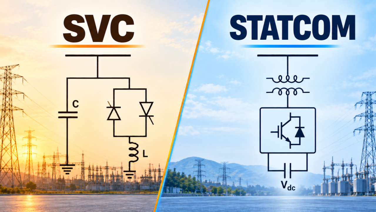
    An SVC is essentially a controlled susceptance. It uses thyristor-controlled reactors and thyristor-switched capacitor branches to change the reactive admittance connected to the system.

    The important point is how its reactive power depends on voltage:

    Q = B × V²

    This becomes critical during a voltage dip. Suppose the PCC voltage falls to 0.5 pu. With the same susceptance, the available reactive power falls approximately with the square of voltage:

    Q = B × (0.5)² = 0.25 pu

    So the SVC may deliver only around 25% of its rated MVAr at 0.5 pu voltage, depending on its configuration. And this happens precisely when the system needs voltage support the most.

    A STATCOM works differently. It is based on a voltage source converter and behaves much more like a controlled current source. Its reactive power can be approximated as:

    Q = V × I

    The relationship with voltage is therefore linear. At 0.5 pu voltage, if the converter maintains its rated reactive current, it can still provide approximately 50% of its rated MVAr.

    This is one of the most important differences between the two technologies. If the main requirement is dynamic voltage support, fault ride-through, post-fault voltage recovery or large-motor starting, the STATCOM has a clear technical advantage because it can maintain much higher reactive current during low-voltage conditions.

    Speed, weak grids and dynamic performance

    Both SVCs and STATCOMs are fast compared with mechanically switched compensation, but their dynamic response is different.

    An SVC is based on thyristor control, so its response is linked to the firing instants of the thyristors. Practical response is typically in the range of one to a few cycles. A modern STATCOM can respond in a few milliseconds, depending on the converter topology and control system.

    For slow changes in system voltage, this difference may not matter much. But consider an arc furnace. Its reactive power demand can change rapidly and repeatedly. The compensator has to follow those changes quickly enough to prevent significant voltage fluctuations at the PCC. This is where the faster response of a STATCOM becomes particularly valuable. The same principle applies to voltage disturbances and post-fault voltage recovery. Weak-grid operation adds another dimension.

    An SVC changes the reactive admittance connected to the grid, so its behavior is strongly influenced by the network impedance behind the PCC. As the grid becomes weaker, the interaction between the compensator and the network becomes more significant, making the control problem more challenging. A STATCOM controls current directly through its converter, giving it better dynamic characteristics in weak systems. This makes it particularly attractive at electrically remote points of connection and at large renewable-energy interconnections.

    Short-circuit strength, often expressed through parameters such as Short Circuit Ratio (SCR), therefore becomes an important part of the technology selection. But SCR should not be treated as a magic number. The actual network impedance, operating conditions, control interactions and required dynamic performance still need to be established through system studies.

    Harmonics and footprint

    An SVC uses thyristor-controlled branches, it generates harmonic currents. Characteristic harmonics such as the 5th, 7th, 11th and 13th therefore become part of the design, and harmonic filters are normally required. These filters introduce additional considerations. They provide fixed capacitive reactive power, can interact with changing network impedance and may create resonance conditions as the network topology changes.

    A modern multilevel STATCOM can produce a much cleaner waveform, which can significantly reduce harmonic filtering requirements and, depending on the design and applicable limits, may eliminate the need for dedicated harmonic filters.

    The physical footprint can also be very different. An SVC installation may require large reactors, capacitor banks and harmonic filters spread across a considerable area. A STATCOM is generally much more compact for the same dynamic compensation requirement. This matters at urban substations, offshore platforms, renewable-energy sites and existing substations where expansion space is limited.

    So where does the SVC still make sense?

    The advantages of STATCOM technology do not make the SVC obsolete. For applications where the main requirement is large amounts of reactive power for steady-state voltage control, an SVC can remain a very practical solution.

    The first advantage is cost. For large ratings, an SVC can offer a lower capital cost per MVAr.

    There is also a difference in losses. A STATCOM has converter conduction and switching losses whenever it is energized, whereas an SVC operating close to zero output can have relatively low losses. If the compensator spends most of its life waiting for a contingency, the lifetime cost of losses becomes important. Over 20 or 25 years, the capitalized value of those losses can materially affect the overall economics.

    SVCs also have decades of operating experience behind them. Utilities are familiar with their protection, control, maintenance and operating philosophy.

    Sometimes the answer is a hybrid

    Real projects do not always have to choose between a large SVC and a large STATCOM. A hybrid solution can sometimes make more sense. For example, a STATCOM can be sized to handle the fast dynamic requirement, while mechanically switched capacitors and reactors, or thyristor-switched branches, provide the bulk of the steady-state MVAr requirement.

    This can provide strong dynamic performance without making the entire reactive power requirement dependent on converter-based compensation.

    The studies that actually decide the technology

    No serious project should select an SVC or STATCOM from a comparison table alone. The network studies should determine what the system actually needs.

    Load flow and V-Q analysis: Establish the required steady-state reactive power range under maximum and minimum load, different generation conditions and contingencies. Light-load conditions are particularly important in cable-rich networks because of the capacitive reactive power generated by the cables.

    Short-circuit study: Establish the short-circuit strength at the Point of Common Coupling and examine how it changes under different network configurations and future system developments. This is particularly important when assessing the suitability of the compensator for a weak grid.

    Dynamic and voltage-stability studies: Examine faults, fault clearance and post-fault voltage recovery. These studies help determine whether the voltage recovers quickly enough, whether induction motors could experience delayed voltage recovery or stalling, and whether inverter-based generation can remain connected.

    Harmonic studies: Evaluate harmonic distortion, filter requirements and possible resonance conditions across credible network configurations. This is particularly important for SVC installations where harmonic filters are normally part of the compensation system.

    Flicker and unbalance studies: These become important for rapidly varying or unbalanced loads. Flicker indicators such as Pst (Short-term Flicker Severity) and Plt (Long-term Flicker Severity), as well as negative-sequence performance, may need to be evaluated depending on the application.

    Loss evaluation: Compare the expected losses over the complete operating life of the installation rather than looking only at the initial purchase price. A device with lower capital cost may not necessarily have the lower lifetime cost.

    The final decision should therefore come from the system studies, operating requirements and lifetime economics, not simply from a technology comparison table. And that is an important distinction: the compensator is selected for the duty it has to perform at the PCC, not simply for the technology it represents.

    And then there is the future

    The grid is rapidly changing. As synchronous generation is replaced or complemented by inverter-based resources, grid-connected power electronic equipment is increasingly being asked to do more than simply provide reactive power.

    A STATCOM is already based on a voltage-source converter. That gives the platform the potential to support additional functionality. Add energy storage, and active-power support becomes possible. Change the control strategy, and the converter can potentially provide grid-forming functionality.

    An SVC was designed around a different fundamental principle. It is a powerful and mature reactive power compensator, but its functionality is centered on controlling reactive admittance. A STATCOM starts with the same basic problem, reactive power and voltage control, but its converter architecture gives engineers a broader platform to build on.

    The real question is not SVC or STATCOM

    The choice between an SVC and a STATCOM is ultimately not about selecting the more advanced technology. It is about matching the characteristics of the compensator to the behavior of the grid.

    Where the requirement is mainly bulk reactive power and steady-state voltage regulation, the simplicity, maturity and economics of an SVC can make it a sensible choice. Where the system demands fast dynamic support, stronger performance during voltage dips, operation in weak-grid conditions, flicker mitigation or a converter platform capable of supporting additional functions, a STATCOM may offer greater value.

    In some applications, the answer may not even be one technology alone. A combination of fast converter-based compensation and conventional reactive power equipment can allow each technology to perform the duty for which it is best suited.

    That is why there is no universal winner in the SVC versus STATCOM debate. The right compensator is the one that meets the actual requirements of the network, both under normal operation and during the disturbances that matter most.
  • What will AI do to Power System Jobs?

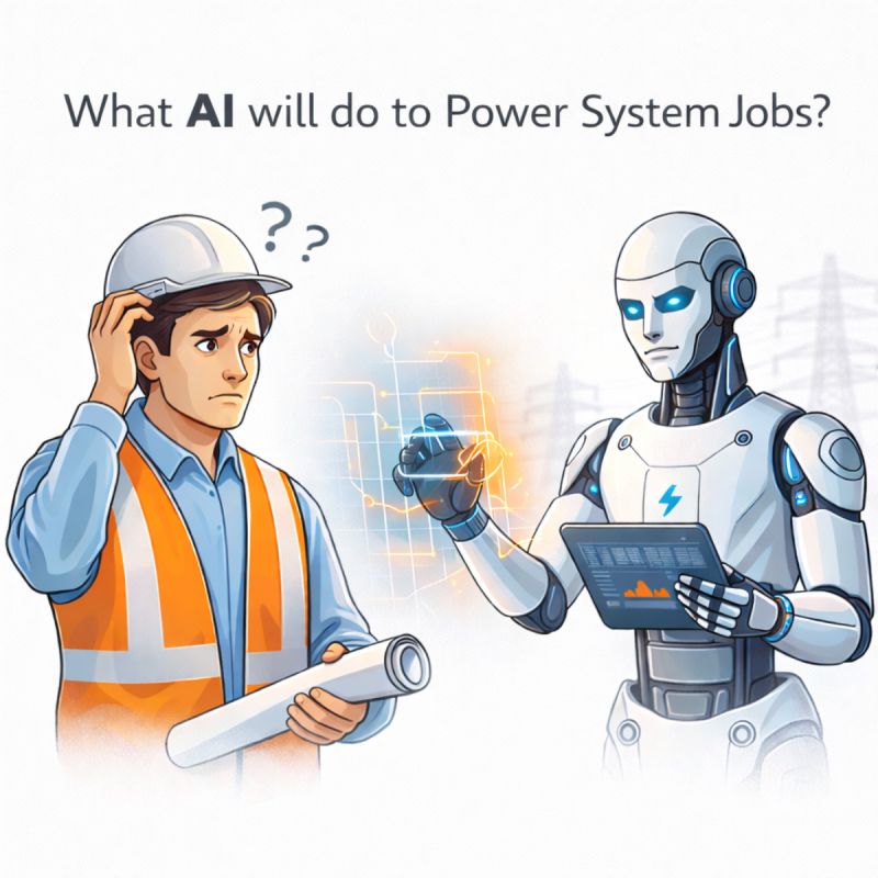
    What will AI do to Power System Jobs?

    It is not possible to predict the future with certainty. What we can do is observe industry trends and understand how power systems are evolving. From that perspective, we can make informed assumptions about where AI may fit into the future of power engineering.

    Jobs that require physical presence in the field, such as commissioning, testing and breakdown maintenance, may not be directly influenced by AI in the near future. A relay still has to be wired. A transformer still has to be tested. Someone still has to stand in the yard and judge whether what the instrument reports matches what the equipment is actually doing. However, roles involving Control and Protection design, verification and validation, RCAs, and fault analysis could see strong influence. These activities are data heavy, logic driven, and increasingly software based.

    It helps to ask what makes a task open to automation in the first place. Work that follows a clear procedure, draws on large amounts of recorded data, and produces an answer that can be checked is the work software reaches first. Going through a week of disturbance records to find the events worth reading is that kind of work. Deciding what the protection philosophy for a new scheme should be is not.

    If we look back 40 or 50 years, power systems were much simpler. Networks were smaller, generation was centralized, and control strategies were basic. Engineers performed load flow calculations, short circuit studies, and stability checks mostly by hand. Engineering judgment was everything, partly because there was little else to lean on. As grids expanded and renewable integration increased, systems became more interconnected and complex. That is when software tools entered the picture. Platforms like MATLAB enabled simulation and control design. Tools such as DIgSILENT PowerFactory, PSCAD, and RTDS became industry standards.

    It is worth remembering what that shift actually did. These tools did not replace engineers. They allowed us to handle larger and more complex networks. What changed was not the need for judgment but the scale at which it could be applied. The engineer who once checked a handful of cases could now check thousands, and the difficult part moved from running the study to choosing which studies mattered and deciding whether the results made sense.

    Now we are entering another phase.

    Future grids will not just be interconnected. They will be intelligent and decentralized. Think about Multi Terminal DC control and protection. Think about DER coordination across thousands of rooftop solar systems. Think about demand response reacting in real time to grid stress. Think about protection that has to work when much of the fault current comes from inverters rather than synchronous machines. Complexity is increasing rapidly, and it is increasing faster than the number of engineers available to manage it.

    AI will likely become another tool, similar to what simulation software once was. It can support predictive maintenance, adaptive protection, real time optimization, anomaly detection, and faster fault interpretation. It can read far more operating data than any team can read by hand, and it can surface the pattern a person would have found eventually, or might have missed altogether. But engineers will still need to design the philosophy, validate outputs, and take responsibility.

    That last point is the one that does not move. When a scheme operates incorrectly and a feeder is lost, the question asked afterwards is not what the software recommended. It is what the engineer decided, and on what basis. A tool can produce an answer. It cannot sign for it.

    AI may change how we work and reduce repetitive analytical tasks. But power systems involve safety, reliability, and accountability. Engineers will not disappear. They will evolve.

    For anyone entering the field now, that evolution is worth preparing for rather than fearing. Learn the fundamentals properly, because you cannot validate an output you do not understand. Get comfortable with data and with scripting, because an engineer who can put a question to a dataset is far more useful than one who waits for a report. And keep the habit of asking why a result looks the way it does, which is the one part of this work that no tool has taken from us.

    The real question is not whether AI will take over power system jobs. The question is whether power system engineers are ready to work alongside AI.

  • The ‘Classic’ LCC HVDC Still Has a Job to Do, and It Isn’t Going Anywhere Yet.

    The ‘Classic’ LCC HVDC Still Has a Job to Do, and It Isn’t Going Anywhere Yet.

    The global transition to renewable energy has introduced one of the greatest geographical puzzles in the history of electrical engineering: the places that generate the most clean energy are rarely the places that consume it. The sunniest deserts and windiest coastlines are often thousands of kilometers away from industrial mega-cities. To bridge this gap, High-Voltage Direct Current (HVDC) transmission has reemerged as the defining infrastructure of the 21st-century grid, allowing operators to move massive amounts of power over vast distances without the crippling reactive power losses associated with alternating current (AC) lines.

    Emergence of VSC HVDC

    In recent years, the engineering community has been heavily focused on the rise of Voltage Source Converter (VSC) HVDC. Because VSC technology utilizes transistors that can be turned on and off electronically, it offers exceptional grid control and flexibility. It doesnt need a strong AC grid to operate; it can black start a dead grid and control both active and reactive power.

    This makes VSC the perfect technology for connecting offshore wind farms to the mainland or feeding power into weak, isolated AC networks. It’s flexible, it has a smaller physical footprint, and it avoids the dreaded commutation failures that plague older tech. As a result, VSC technology has seen a massive surge in adoption over the past decade.

    The Reign of LCC HVDC is Not Yet Over

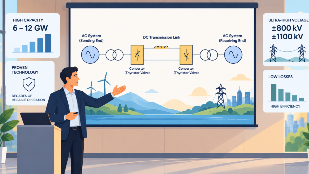
    However, despite the clear operational advantages of VSC, the original standard for DC transmission, Line-Commutated Converter (LCC) HVDC, remains fundamentally indispensable. LCC technology, which utilizes robust thyristor valves, is sometimes viewed as classic technology, yet it continues to serve as the backbone for the world’s highest-capacity transmission corridors.

    The primary technical divergence between the two technologies lies in power handling and efficiency. While state-of-the-art VSC systems are currently pushing capacities of 2 to 3 Gigawatts (GW), modern LCC systems routinely handle 6 to 12 GW. Furthermore, LCC has successfully scaled to Ultra-high voltage (UHVDC) levels of ±800 kV and ±1100 kV.

    Market Reality: Project Count vs. Transformation Capacity

    The current market dynamic is a fascinating tale of two metrics: project volume versus transformation capacity. If you look at the sheer number of new projects globally, VSC is taking the lions share. Between 2023 and 2025, roughly 62% of new HVDC project announcements incorporated VSC technology. This shift is heavily driven by the boom in European offshore wind grids and point-to-point interconnectors, where VSCs footprint and modularity are necessary. However, if you measure by bulk GW capacity, LCC still holds a massive, irreplaceable footprint. The world’s biggest energy corridors, the true mega-projects, still rely on thyristor-based LCC technology to do the heavy lifting.

    India and China are investing heavily in LCC HVDC technology. India has recently announced major LCC HVDC projects as part of its plans to evacuate large amounts of renewable energy over long distances. Key initiatives include the ±800 kV 6000 MW Bhadla–Fatehpur link, which will transmit renewable power from the Bhadla renewable energy zone in Rajasthan towards Fatehpur in Uttar Pradesh. Similarly, the ±800 kV 6000 MW Barmer South–Kalamb corridor is being developed to transfer green energy from western Rajasthan to South Kalamb in Maharashtra. Additionally, the ±800 kV 6000 MW Khavda–Nagpur project is currently under construction to further strengthen this high-capacity grid infrastructure. China is also actively planning and building massive LCC-HVDC (and hybrid LCC-VSC) projects to connect remote renewable energy hubs to its major metropolitan centers.

    The Backbone of the Future Grid

    The evolution of HVDC is not a strict replacement of LCC by VSC, but rather a bifurcation of applications based on specific system requirements. VSC is the optimal choice for system flexibility, multi-terminal networks, and offshore integration. However, for point-to-point, ultra-high-capacity transmission over continental distances, the low losses and high voltage ratings of thyristor-based LCC technology remain unmatched.

    As the global energy transition accelerates and the need to transport gigawatts of clean energy across continents grows, LCC HVDC will continue to play a crucial role in modern grid infrastructure for decades to come.

  • New Transmission Line or FACTS Device: Which Would You Choose?

    New Transmission Line or FACTS Device: Which Would You Choose?

    Imagine a city where traffic congestion is getting worse. The first thought might be simple: build another highway.

    But what if a large part of the congestion is caused by unnecessary traffic using the existing roads? Or what if the roads themselves could be modified to allow traffic to move more efficiently? In that situation, building a completely new highway may not always be the first or best solution. Better traffic management and improvements to existing roads could increase the useful capacity of the infrastructure already available.

    Something very similar happens in power transmission.

    As electricity demand increases and more renewable generation is connected to the grid, transmission lines can become heavily loaded. The obvious solution is to build new transmission lines. But before doing that, engineers need to ask an important question:

    Is the transmission corridor really short of physical capacity, or can the existing network be used more effectively?

    This is where reactive power compensation and FACTS technologies become important. Consider a transmission line supplying a large load. The load does not consume only active power. Inductive loads such as motors and transformers also require reactive power. If reactive power has to travel over a long transmission line from a remote source, it contributes to the current flowing through the line. The higher current increases (I^2R) losses and causes a larger voltage drop.

    Now imagine that reactive power support is provided close to the load.

    A shunt capacitor, SVC or STATCOM can supply part of the required reactive power locally. The transmission line then does not need to carry as much reactive power from the remote generation area. This can reduce the current flowing through the transmission line. And that matters because the thermal limit of a transmission line is fundamentally related to current. For the same amount of active power being delivered, reducing unnecessary reactive-power flow can therefore reduce line current and losses and potentially free up some of the lines current-carrying capability for active power transfer.

    This is one of the important reasons why local reactive power compensation can be valuable.

    But there is another way to increase the capability of an existing transmission line.

    Instead of reducing the current associated with reactive power flow, what if we reduce the electrical opposition to power transfer itself?

    This is the basic idea behind series compensation.

    A transmission line has series reactance. In a simplified lossless transmission model, the active power transfer is inversely proportional to the series reactance of the transmission path. If the effective series reactance (X) is reduced using series compensation, the theoretical power-transfer capability increases. This is why devices such as TCSC (Thyristor Controlled Series Capacitor) and SSSC (Static Synchronous Series Compensator) are important. By controlling the effective series reactance of a transmission line, they can increase power-transfer capability and influence how power is distributed between parallel transmission corridors.

    In simple terms, shunt compensation and series compensation solve different problems.

    Shunt compensation mainly supports voltage and provides reactive power close to where it is needed. Series compensation reduces the effective impedance of the transmission path and can increase its power-transfer capability.

    Modern FACTS technology can combine these capabilities with fast dynamic control.

    However, this does not mean that FACTS can replace every new transmission line.

    If a corridor has reached its fundamental thermal limit, reducing reactance does not mean that the conductor can safely carry unlimited current. A new transmission line may still be necessary.

    Similarly, the actual power-transfer limit of a transmission corridor depends on much more than the simplified relationship between power transfer and line reactance. Voltage stability, transient and dynamic stability, equipment thermal ratings, protection requirements, and the overall operating condition of the network all have to be considered.

    This is why the decision should not simply be “new transmission line or FACTS?”

    The better question is:

    “What is actually limiting the transmission corridor?”

    If the problem is a lack of physical transmission capacity, building a new line may be the right answer. If the problem is voltage support and excessive reactive-power flow, local shunt compensation may help. If the limitation is related to transmission reactance and power-transfer capability, series compensation may provide a solution.

    And sometimes the best answer is a combination of all three.

    The future grid will need both more transmission infrastructure and better use of the infrastructure already available. Just as a growing city may need new highways while also improving traffic management on existing roads, the power system may need new transmission lines while using technologies such as SVC, STATCOM and TCSC to extract more useful capability from existing transmission corridors.

    The real engineering challenge is therefore not simply to build more.

    It is to understand what is limiting the grid, and then choose the right solution for that particular limitation.

  • From Rotating Mass to Algorithms: The Changing Character of Inertia in Power Grids

    From Rotating Mass to Algorithms: The Changing Character of Inertia in Power Grids

    For decades, inertia was an inherent feature of power systems, provided automatically by large rotating machines. As power grids evolve toward inverter-dominated architectures, inertia is no longer guaranteed by physics and increasingly depends on how systems are designed and controlled. Understanding why inertia matters is the first step in understanding how its character is changing.

    Why Inertia Matters?

    Frequency in a power system is a direct reflection of the balance between generation and demand. Any sudden mismatch—such as the loss of a generator, a large load connection, or a network disturbance—causes the system frequency to deviate from its nominal value. If generation falls short of demand, frequency begins to decline; if generation exceeds demand, it rises. These frequency changes are not just numerical deviations but clear signs of stress in the system. Rapid frequency excursions can lead to protection maloperation, unwanted tripping of generators and loads, and in extreme cases, cascading outages and system collapse. The faster the frequency changes, the less time is available for controls, reserves, and operators to act. This is where inertia matters: it is the ability of the power system to slow down the rate of frequency change, giving the grid the time it needs to respond and stay stable.

    Natural Inertia in Conventional Power Systems

    In conventional power systems, inertia is mainly provided by synchronous generators connected directly to the grid. These machines have large rotating masses, such as turbines and generator rotors, which store kinetic energy while operating at synchronous speed. When a disturbance occurs and frequency starts to change, this stored kinetic energy is released or absorbed automatically, without any control action or delay. This inherent physical response opposes rapid frequency changes and provides an immediate stabilizing effect. Because this inertia is tied directly to the machine’s mass and speed, it is always available as long as the generator is connected and synchronized to the grid. This immediate response plays a critical role in the first few seconds following a disturbance, when no control system or reserve has yet had time to act. During this period, inertia limits the rate at which frequency changes, preventing sudden and extreme deviations. For instance, after the sudden loss of a large generator, the kinetic energy released by other synchronized machines helps supply the shortfall, slowing the frequency decline. Similarly, following a sudden loss of load, the machines absorb excess energy, restraining a rapid rise in frequency. By moderating these initial dynamics, inertia creates a stable time window that allows primary frequency control, protection systems, and operator actions to respond in an orderly manner.

    Declining Inertia in Modern Power Systems

    In modern power systems, the amount of available inertia is steadily reducing as synchronous generators are replaced by inverter-based resources such as wind, solar PV, and battery energy storage systems. These resources connect to the grid through power electronic converters, so system frequency is no longer directly tied to any rotating mass and physical inertia is not naturally available. As a result, the grid experiences faster frequency changes following disturbances, higher rates of change of frequency, and reduced time margins for protection and control actions. This shift increases the risk of unintended protection trips, challenges frequency containment, and places greater dependence on fast-acting controls and reserves. Grid operation therefore becomes more sensitive to disturbances, requiring tighter coordination, improved monitoring, and deliberate design of frequency support mechanisms.

    Synthetic Inertia in Inverter-Based Power Systems

    In low-inertia grids, synthetic inertia is provided through control strategies implemented in inverter-based resources. These strategies rely on algorithms that continuously monitor system frequency and its rate of change, and command the inverter to quickly inject or absorb power following a disturbance. This fast power response is designed to oppose rapid frequency changes in a manner similar to the inertial behavior of synchronous generators. The energy used for this response does not come from rotating masses, but from the energy source connected on the DC side of the inverter, such as batteries, wind turbine kinetic energy, or stored electrical energy in DC-link capacitors. In conventional generators, large rotating masses naturally played the role of energy buffers. In inverter-based systems, this role is taken over by controlled energy sources enabled by fast power electronics, making inertia an actively managed feature rather than a passive physical property of the grid.

    While synthetic inertia can significantly improve frequency response and support grid stability, it introduces new challenges related to coordination, energy limits, and interaction with protection systems. As inertia transitions from a passive physical characteristic to a feature shaped by control design, careful system-level engineering becomes essential to ensure reliable and predictable grid operation.

  • Beyond the Binary: A Phased Roadmap for Nuclear and Renewables

    Beyond the Binary: A Phased Roadmap for Nuclear and Renewables

    The global energy transition is often presented as a binary choice: the clean promise of renewables versus the stable power of nuclear. This framing oversimplifies a complex engineering and human challenge. Deciding our energy future is not just about technology; it is a negotiation between our desire for safety, our fear of risk, and our relentless drive for economic efficiency. The current debate is trending because these human factors are clashing in real time.

    The Pull Towards Ultimate Safety

    If we look into the future, the ultimate convergence point for electricity generation appears to be a fully renewable grid. This aligns perfectly with a fundamental human trait: the desire for absolute safety and zero risk to life. Events like Chernobyl and Fukushima have embedded a deep-seated fear of catastrophic nuclear accidents in our collective consciousness. In an age dominated by social media and instant information, public pressure to eliminate any perceived risk will only increase. This pressure pushes policy makers and investors away from nuclear power, despite its clear low-carbon benefits, because the social and political risk profile is simply too high. We want energy that is abundant, cheap, and, crucially, harmless.

    The Scalability Challenge of Intermittent Renewables

    However, the transition faces immediate, practical hurdles that challenge our goal of economic optimization. The primary issue with solar and wind power is intermittency—the sun does not always shine, and the wind does not always blow. To achieve a reliable, fully renewable grid, we need vast Battery Energy Storage Systems (BESS) and other long-duration storage solutions.

    At present, utility-scale BESS is highly effective for short-term grid balancing but is not yet scalable or affordable enough to power entire nations for days or weeks without wind or sun. The sheer material and cost requirements for storing that much energy are astronomical today. Relying solely on renewables right now would force us to burn more natural gas for reliability, defeating the purpose of decarbonization.

    The Necessary Bridge: A Phased Approach

    We are in a carbon reduction crisis, and we need dispatchable, low-carbon power now. This is where the pragmatic choice of existing nuclear and hydro power becomes essential for a temporary period. The risks associated with nuclear energy are real and cannot be completely eliminated, but they can be managed with robust engineering and regulation. We must weigh the immediate, widespread risk of climate change against the localized, albeit severe, risk of a nuclear incident.

    The most probable scenario is a strategic, phased shift. While some argue that advanced nuclear designs may retain a long-term role, the dominant societal trajectory points toward minimizing technologies with catastrophic failure modes. In the near to medium term, nuclear power will provide essential baseload generation, acting as a critical bridge to manage the intermittency of the rapidly expanding wind and solar sectors. This provides grid stability while simultaneously replacing fossil fuels.

    The Eventual Convergence

    This is not a permanent solution, but a carefully managed transition. The roadmap involves leveraging nuclear today until storage technologies, BESS, and other renewable innovations mature enough to ensure 100% reliability at scale. The pressure to minimize systemic and catastrophic risk will increasingly shape energy choices for the future.

    The global energy strategy is not about choosing a winner between nuclear or renewables; it is about sequencing their deployment effectively. The ultimate convergence point will be a fully renewable grid, but nuclear power provides the essential stability required to get us there responsibly and reliably.

  • What Is InterOPERA and Why Are Utilities Betting Big on It?

    What Is InterOPERA and Why Are Utilities Betting Big on It?

    1. What is InterOPERA?

    InterOPERA is a large international project that focuses on making future HVDC systems interoperable. The project runs from 1 January 2023 to 30 April 2027. It brings together transmission operators, offshore wind developers, HVDC manufacturers, research institutes, and universities. The aim is to create practical technical requirements so that converters, protection systems, and control systems from different manufacturers can work together as part of the same HVDC grid.

    In simple terms, InterOPERA wants future HVDC systems to behave like today’s AC systems where equipment from different suppliers can operate together without major compatibility issues.

    2. What is the scenario of interoperability in HVDC today?

    Today, HVDC interoperability is very limited. Most HVDC links are designed by a single vendor and follow that vendor’s own control and protection philosophy. This leads to several problems:

    Interfaces and communication methods differ from one supplier to anotherProtection schemes do not follow a common approachMulti-terminal HVDC systems are difficult to design and testCombining equipment from multiple vendors requires special engineering and long testing cycles

    Because of these issues, it is difficult to build a large, flexible HVDC network that can support offshore wind, cross-border transmission, and future power corridors. The lack of interoperability increases cost and slows down the adoption of HVDC technology worldwide.

    3. Do AC systems have interoperability?

    AC power systems already operate in a highly interoperable manner. This is possible because clear standards, shared grid codes, and well-established communication protocols exist. Equipment from different manufacturers can be connected to the same grid and is expected to behave predictably.

    Transformers, breakers, relays, meters, and protection systems from various suppliers work together in AC grids because the industry has spent many decades aligning designs and defining common requirements. This level of maturity does not yet exist for HVDC systems. InterOPERA aims to close this gap and create the foundation for HVDC systems that are as interoperable as AC systems.

    4. What are the objectives of InterOPERA?

    According to the project website, InterOPERA is built around six clear objectives:

    To make HVDC grids modular and interoperable by design.To standardize HVDC and wind power plant simulation models for assessment of interoperability.To perform a real-time physical demonstration of a multi-vendor control and protection system, including grid forming control capability.To pave the way to real-life Multi-Vendor, Multi-Terminal HVDC applications ready for future seamless system extension.To develop grid forming control features to support onshore AC systems.To secure multi-stakeholder cooperation, build confidence and uptake of the interoperability frameworks.

    4. How will InterOPERA change the grid at a global level?

    If InterOPERA succeeds, it will influence the development of HVDC grids not only in Europe but around the world. Several major changes are expected:

    Multi-vendor HVDC projects will become easier to design and operate. Utilities will no longer have to rely on a single supplier for an entire HVDC project.International standards will strengthen because InterOPERA’s methods and test procedures can serve as valuable references for organizations such as IEC.Offshore wind integration will improve globally. Countries planning large offshore zones will be able to use proven interoperable HVDC designs.Costs will fall as standardization reduces the need for custom engineering and complex vendor-specific integration.Manufacturers will align their designs to match the new common requirements, which will naturally create a more harmonized global HVDC market.Long-term energy visions such as regional supergrids or international renewable energy corridors will become more realistic once HVDC systems are compatible by design.